H无穷大状态观测器设计与仿真

系统模型

本文介绍如下形式线性系统的状态观测器设计:

系统模型

相比于标准状态空间模型,还考虑了扰动信号\(w(t)\)的影响。\(y(t)\)是测量输出,可看成是传感器系统模型,\(z(t)\)是系统输出。目标是设计一个全阶状态观测器,使得扰动信号\(w(t)\)对状态估计误差的影响足够小。

状态观测器设计

采用如下形式的观测器:

状态观测器的形式

稍微推算下就能发现,\((9.23)\)\((1)(2)\)所描述的观测器等价:

\[ \dot{\hat{x}}=A\hat{x}+B_1u-L(y-\hat{y}) \tag{1} \] \[ \hat{y}=C_1\hat{x}+D_1u \tag{2} \]

它其实就是倒立摆的状态观测器设计中采用的Luenberger状态观测器,仅仅只是正负号不同,在理论分析和仿真时要注意这点。接下来便是一些常规的理论推导:

观测器的理论推导

\((9.25)\)所示的动态方程描述了状态估计误差\(e\)和系统输出估计误差\(\tilde{z}\)之间的关系。还得到了从\(w\)\(\tilde{z}\)的传递函数\(G_{\tilde{z}w}(s)\),要使它的\(H_{\infty}\)范数尽量小,就能抑制扰动信号对系统输出估计误差的影响。

问题描述

下图中的问题\((9.3)\)描述了\(H_{\infty}\)状态观测器的目标,如果\(\lVert G_{\tilde{z}w}(s) \rVert_{\infty}<\gamma\),那么状态估计误差\(e\)就会趋于零。

H无穷大状态观测器问题描述

观测器反馈矩阵

接下来要求解状态观测器反馈矩阵\(L\),有如下定理:

观测器反馈矩阵计算的定理

求解上面的线性矩阵不等式(LMI)问题即可得到\(L\)矩阵,可以在MATLAB中使用YALMIP求解。

状态反馈控制器

接下来利用观测器得到的状态估计\(\hat{x}\)设计控制器,采用如下状态反馈控制律,为和前面的\(A+LC_1\)在形式上保持一致,没有加负号:

\[ u=K\hat{x} \tag{3} \]

根据控制性能指标要求选取合适的\(K\)矩阵。将\((3)\)代入到\((9.22)\)中可得

\[ \dot{x}=(A+B_1K)x+B_1Ke+B_2w \tag{4} \]

\((9.25)\)\((4)\)合并,得到如下矩阵方程

\[ \left[ \begin{array}{c} \dot{x}\\ \dot{e}\\ \end{array} \right] =\left[ \begin{matrix} A+B_1K& B_1K\\ 0& A+LC_1\\ \end{matrix} \right] \left[ \begin{array}{c} x\\ e\\ \end{array} \right] +\left[ \begin{array}{c} B_2\\ B_2+LD_2\\ \end{array} \right] w \tag{5} \]

系统状态\(x\)和状态估计误差\(e\)可以在仿真中直接得到,为了看到输出估计误差,将系统输出方程设置为

\[ \tilde{z}=\left[ \begin{matrix} 0& C_2\\ \end{matrix} \right] \left[ \begin{array}{c} x\\ e\\ \end{array} \right] \tag{6} \]

根据\((5)(6)\)即可设计基于状态估计的反馈控制器。

仿真设计与结果

最后通过仿真验证\(H_{\infty}\)状态观测器对扰动信号\(w(t)\)的抑制能力。最好将\(L\)矩阵的求解、观测器设计和控制器设计的代码放到同一个文件中,这样就能使用最精确的\(L\)矩阵。MATLAB的默认输出精度是小数点后4位,根据我的经验,\(L\)的舍入误差对观测器性能影响较大。

下面的代码带有矩阵维数检查,对于不同的模型,只需要做少量修改既可运行:

1
2
3
4
5
6
7
8
9
10
11
12
13
14
15
16
17
18
19
20
21
22
23
24
25
26
27
28
29
30
31
32
33
34
35
36
37
38
39
40
41
42
43
44
45
46
47
48
49
50
51
52
53
54
55
56
57
58
59
60
61
62
63
64
65
66
67
68
69
70
71
72
73
74
75
76
77
78
79
80
81
82
83
84
85
86
87
88
89
90
91
92
93
94
95
%% Model described by (9.22)
n = 3; % dimension of state x
l = 2; % dimension of measured state y
m = 2; % dimension of output z
p = 1; % dimension of disturbance w
r = 2; % dimension of input u

% n by n matrix
A = [2.8982, -3.1606, 0.6816;
6.3595, -4.2055, 4.5423;
3.2046, -3.1761, -3.8142];
if ~isequal(size(A), [n, n])
fprintf('Dimension of A is wrong!!\n');
end
% n by r matrix
B1 = [2.0310, 1.2164;
0.4084, 0.2794;
-0.7775, -0.3307];
if ~isequal(size(B1), [n, r])
fprintf('Dimension of B1 is wrong!!\n');
end
% n by p matrix
B2 = [-0.0785;
-0.0853;
-0.0986];
if ~isequal(size(B2), [n, p])
fprintf('Dimension of B2 is wrong!!\n');
end
% l by n matrix
C1 = [-0.8778, -4.9442, -4.5084;
4.0161, -2.0259, 1.9318];
if ~isequal(size(C1), [l, n])
fprintf('Dimension of C1 is wrong!!\n');
end
% l by r matrix
D1 = [0.6004, 0.2107;
1.9320, -0.3997];
if ~isequal(size(D1), [l, r])
fprintf('Dimension of D1 is wrong!!\n');
end
% l by p matrix
D2 = [0.0330;
-0.0414];
if ~isequal(size(D2), [l, p])
fprintf('Dimension of D2 is wrong!!\n');
end
% m by n matrix
C2 = [0.9607, 1.5600, 2.8558;
-2.4371, 1.3634, 0.0095];
if ~isequal(size(C2), [m, n])
fprintf('Dimension of C2 is wrong!!\n');
end

%% Solve LMI to get L
yalmip('clear')

gamma = 1e-8;
P = sdpvar(n, n);
W = sdpvar(n, l, 'full');
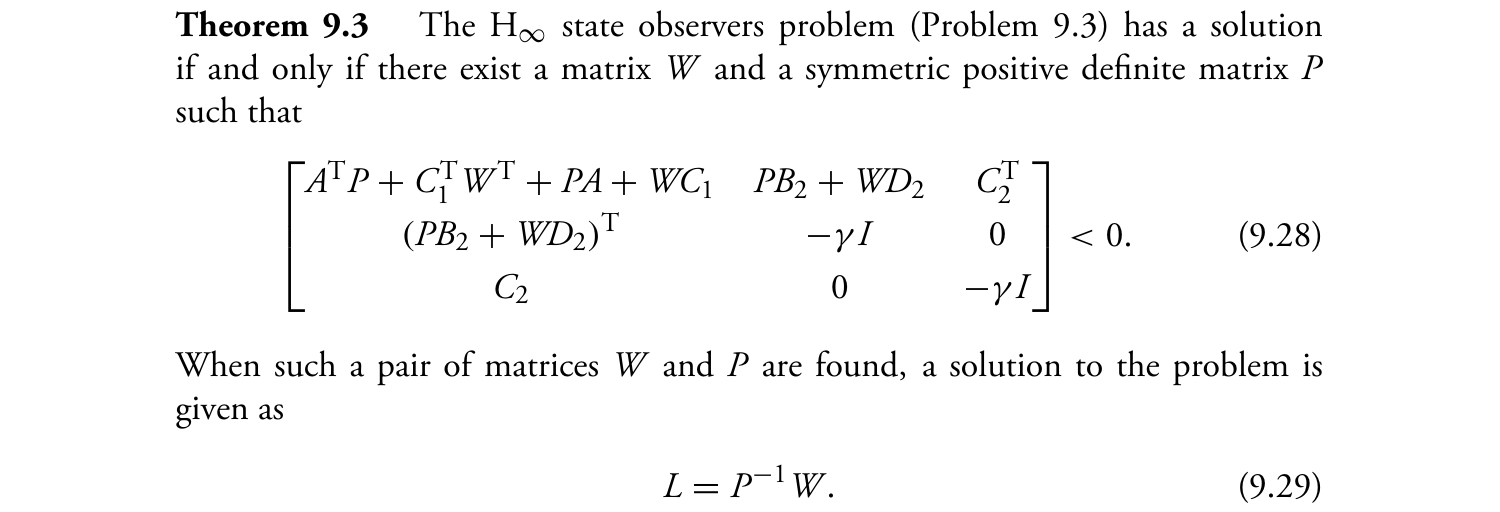
M = [A'*P+C1'*W'+P*A+W*C1, P*B2+W*D2, C2';
(P*B2+W*D2)', -gamma*eye(p), zeros(p, m);
C2, zeros(m, p), -gamma*eye(m)];

Constraints = [P >= 0; M <= 0];
Objective = [];
options = sdpsettings('verbose', 0); % 1: print verbose
sol = optimize(Constraints, Objective, options);

if sol.problem == 0
L = value(P)\value(W);
else
disp('Hmm, something went wrong!');
sol.info
yalmiperror(sol.problem)
end

%% State observer, observer-based controller
% Pole placement to get K
poles = [-5; -7+7j; -7-7j];
K = place(A, -B1, poles);
% Build the model of (5)(6)
Aco = [A+B1*K, B1*K;
zeros(size(A)), A+L*C1];
Bco = [B2; B2+L*D2];
Cco = [zeros(size(C2)), C2]; Dco = 0;
sys_co = ss(Aco, Bco, Cco, Dco);
% Run lsim to simulate
t = 0:0.01:4;
xe0 = zeros(6, 1);
w = wgn(1, length(t), 100, 'real'); % while noise with power of 100dBW
[zt, t, xe] = lsim(sys_co, w, t, xe0); % save output in zt, save state in xe
% Plots
subplot(311); plot(t, w, 'LineWidth', 1); grid on
subplot(312); plot(t, xe(:, 4:6), 'LineWidth', 1); grid on
subplot(313); plot(t, zt(:, 1:2), 'LineWidth', 1); grid on

得到扰动信号\(w(t)\)、状态估计误差\(e(t)\)和输出估计误差\(\tilde{z}(t)\)随时间变化的曲线如下:

状态观测器性能

很明显,所设计的\(H_{\infty}\)状态观测器对扰动信号\(w(t)\)有很强的抑制能力,达到了\((9.26)\)要求的性能。

参考资料

  1. LMIs in Control Systems
  2. 现代控制工程